Camera Rays
Suppose you want to path (or ray) trace a scene using GLSL. You set up a full screen quad and pass it through your vertex shader into your fragment shader. What's next? Typically, you generate a camera ray, a ray that starts at your camera position and passes through the fragment being rendered. There are several ways to skin this cat, and honestly, none of the ones I've come across feel particularly elegant. In this post, I'll be presenting what I've settled on as an efficient and reasonably intuitive method - my best of the bad, if you will.
Overview
We'll be covering two ways to use this method - the perspective and orthographic projections. We'll need a few things that are common to both of these:
- Full screen quad: A vertex attribute that defines the position of vertices composing two triangles that cover the entire rendering surface.

2D position vertices describing a full screen quad.
- Camera position: The world-space position (x, y, z) of the camera.
- Camera center: The world-space point (x, y, z) that the camera is looking at.
- Up vector: The three dimensional vector that defines up. There is some overlap with this quantity and the vector defined by the camera position and camera center. In this formulation, the up vector will be used to extract a roll, but not a pitch.
- Aspect ratio: This is the rendering surface width divided by its height. Units don't matter here, so pixels (or whatever else you want) for the width and height are fine.
For both projections we'll be creating a new vertex attribute of the same size and type as the full screen quad, but it will represent the vertices defining a quad perpendicular to the view direction and intersecting the viewing frustum. For lack of a better term, I'll dub this the ray quad. We'll use the graphics pipeline to interpolate across the ray quad in world space and use the fragment positions to construct a camera ray.
Symbols
Here's a table of symbols you can reference while reading.
| Symbol | Description |
|---|---|
| $\boldsymbol{\hat{f}}$ | The normalized forward direction of the camera. |
| $\boldsymbol{\hat{u}}$ | The normalized up direction of the camera. Used to define roll, but not pitch. |
| $\boldsymbol{\hat{r}}$ | The normalized right direction of the camera. |
| $\boldsymbol{a}$, $\boldsymbol{b}$, $\boldsymbol{c}$, $\boldsymbol{d}$ | Each vertex of the full screen quad. |
| $\boldsymbol{a}'$, $\boldsymbol{b}'$, $\boldsymbol{c}'$, $\boldsymbol{d}'$ | Each vertex of the ray quad. |
| $\boldsymbol{C}_p$ | Camera position. The position of the camera in world space. |
| $\boldsymbol{C}_c$ | Camera center. The point in world space the camera is looking at. |
| $w$, $h$ | The width and height of the rendering surface in any units. |
| $a$ | The aspect ratio of the rendering surface. |
| $\theta$ | The vertical field of view in radians. Used only in the perspective projection. |
| $m_u$, $m_d$, $m_l$, $m_r$ | The magnitude of the up, down, left, and right offsets from the center of the ray quad. |
| $\alpha$ | The scale of the orthographic projection. |
Did I miss one? Hit me up on twitter and I'll fill it in.
Perspective Projection
The first projection we'll handle is the perspective projection. For this, we'll need to define a vertical field of view, or $\theta$. Once we have that, the first step will be to calculate the normalized forward vector from the camera position and camera target.
$$\boldsymbol{\hat{f}} = \frac{\boldsymbol{C}_c - \boldsymbol{C}_p}{\left| \boldsymbol{C}_c - \boldsymbol{C}_p \right|}$$
Next we'll calculate the normalized right vector from forward and up:
$$\boldsymbol{\hat{r}} = \frac{\boldsymbol{\hat{f}} \times \boldsymbol{\hat{u}}}{\left| \boldsymbol{\hat{f}} \times \boldsymbol{\hat{u}} \right|}$$
Then we'll update the up vector so that it's consistent with forward and right:
$$\boldsymbol{\hat{u}} = \frac{\boldsymbol{\hat{r}} \times \boldsymbol{\hat{f}}}{\left| \boldsymbol{\hat{r}} \times \boldsymbol{\hat{f}} \right|}$$
Next we need to calculate how far up, down, left, and right we need to move from the center of the ray quad to reach each of the four corners. If we assume the ray quad intersects the view frustum one unit away from the camera position, the math boils down to this:
$$ \begin{align} m_u & = tan(\frac{\theta}{2}) \\ m_d & = -m_u \\ m_r & = \frac{w \cdot m_u}{h} \\ m_l & = -m_r \end{align} $$
Now we can calculate the vertex positions of the ray quad:
$$ \begin{align} \boldsymbol{a}' & = \boldsymbol{C}_p + \boldsymbol{\hat{f}} + m_d \boldsymbol{\hat{u}} + m_l \boldsymbol{\hat{r}}\\ \boldsymbol{b}' & = \boldsymbol{C}_p + \boldsymbol{\hat{f}} + m_d \boldsymbol{\hat{u}} + m_r \boldsymbol{\hat{r}}\\ \boldsymbol{c}' & = \boldsymbol{C}_p + \boldsymbol{\hat{f}} + m_u \boldsymbol{\hat{u}} + m_r \boldsymbol{\hat{r}}\\ \boldsymbol{d}' & = \boldsymbol{C}_p + \boldsymbol{\hat{f}} + m_u \boldsymbol{\hat{u}} + m_l \boldsymbol{\hat{r}} \end{align} $$

Calculating the 3D vertex positions $\boldsymbol{a}'$, $\boldsymbol{b}'$, $\boldsymbol{c}'$, and $\boldsymbol{d}'$ describing the perspective ray quad.
Let's take a look at some code. First, a function that finds $\boldsymbol{a}'$, $\boldsymbol{b}'$, $\boldsymbol{c}'$, and $\boldsymbol{d}'$ and constructs a vertex attribute array from them:
function rayQuad(Cp, Cc, up, fov, aspect) {
  // Caluclate the normalized forward direction.
  const forward = vec3.normalize([], vec3.sub([], Cc, Cp));

  // Calculate the normalized right direction.
  const right = vec3.normalize([], vec3.cross([], forward, up));

  // Recalculate the normalized up direction.
  vec3.normalize(up, vec3.cross([], right, forward));

  // Calculate how far up, down, left, and right we need to move from the
  // center of the ray quad to find points a', b', c', and d'.
  const mu = Math.tan(fov / 2);
  const md = -mu;
  const mr = aspect * mu;
  const ml = -mr;

  // Calculate Cp + forward to find the center of the ray quad.
  const Z = vec3.add([], Cp, forward);

  // Define vectors along up and right of lengths ml, mr, mu, and md.
  const muUp = vec3.scale([], up, mu);
  const mdUp = vec3.scale([], up, md);
  const mrRight = vec3.scale([], right, mr);
  const mlRight = vec3.scale([], right, ml);

  // Find points a', b', c', and d'.
  const a = vec3.add([], Z, vec3.add([], mdUp, mlRight));
  const b = vec3.add([], Z, vec3.add([], mdUp, mrRight));
  const c = vec3.add([], Z, vec3.add([], muUp, mrRight));
  const d = vec3.add([], Z, vec3.add([], muUp, mlRight));

  // Construct an unindexed vertex attribute array from a', b', c', and d'.
  const uv = [];
  uv.push(...a);
  uv.push(...b);
  uv.push(...c);
  uv.push(...a);
  uv.push(...c);
  uv.push(...d);

  // Return the array.
  return uv;
}
Next, the vertex shader:
  attribute vec2 position; // The full screen quad vertex attribute.
  attribute vec3 rayQuad;  // The ray quad vertex attribute.
  varying vec3 vRayQuad;   // We'll interpolate over the ray quad with this.

  void main() {
    // Ray quad interpolation.
    vRayQuad = rayQuad;

    // Set the vertex position.
    gl_Position = vec4(position, 0, 1);
  }
Finally, the fragment shader:
  varying vec3 vRayQuad; // The ray quad interpolated fragment.
  uniform vec3 Cp;       // The camera position.

  void main() {
    // Calculate the ray.
    vec3 ray = normalize(vRayQuad - Cp);

    // Ray origin is Cp.

    ...
  }
Note that in addition to the ray quad vertex attribute, we also need to pass in the camera position $\boldsymbol{C}_p$ in order to calculate the ray direction.
Using the above code, we can perform ray-sphere intersection tests to ray trace some spheres:
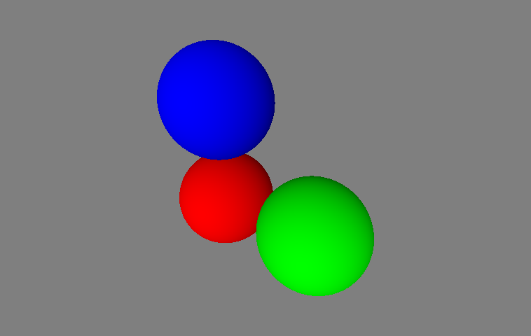
Ray tracing spheres with perspective camera rays.
Orthographic Projection
Calculating the ray quad for the orthographic projection is very similar to the calculation for the perspective projection. We'll need a scale quantity, $\alpha$, that describes the extents of the orthographic projection. Once we have that, we can start by calculating the forward, up, and right unit vectors in the same way we did for the perspective projections:
$$ \begin{align} \boldsymbol{\hat{f}} & = \frac{\boldsymbol{C}_c - \boldsymbol{C}_p}{\left| \boldsymbol{C}_c - \boldsymbol{C}_p \right|}\\ \boldsymbol{\hat{r}} & = \frac{\boldsymbol{\hat{f}} \times \boldsymbol{\hat{u}}}{\left| \boldsymbol{\hat{f}} \times \boldsymbol{\hat{u}} \right|}\\ \boldsymbol{\hat{u}} & = \frac{\boldsymbol{\hat{r}} \times \boldsymbol{\hat{f}}}{\left| \boldsymbol{\hat{r}} \times \boldsymbol{\hat{f}} \right|} \end{align} $$
Then we'll calculate $m_u$, $m_d$, $m_l$, and $m_r$, but we'll use $\alpha$ instead of the field of view:
$$ \begin{align} m_u & = \alpha\\ m_d & = -\alpha\\ m_r & = \frac{w \cdot m_u}{h}\\ m_l & = -m_r \end{align} $$
And finally calculate the vertex positions of the ray quad:
$$ \begin{align} \boldsymbol{a}' & = \boldsymbol{C}_p + m_d \boldsymbol{\hat{u}} + m_l \boldsymbol{\hat{r}}\\ \boldsymbol{b}' & = \boldsymbol{C}_p + m_d \boldsymbol{\hat{u}} + m_r \boldsymbol{\hat{r}}\\ \boldsymbol{c}' & = \boldsymbol{C}_p + m_u \boldsymbol{\hat{u}} + m_r \boldsymbol{\hat{r}}\\ \boldsymbol{d}' & = \boldsymbol{C}_p + m_u \boldsymbol{\hat{u}} + m_l \boldsymbol{\hat{r}} \end{align} $$

Calculating the 3D vertex positions $\boldsymbol{a}'$, $\boldsymbol{b}'$, $\boldsymbol{c}'$, and $\boldsymbol{d}'$ describing the orthographic ray quad.
The code for the orthographic projection is, again, very similar to that of the perspective projection. Let's take a look.
function rayQuad(Cp, Cc, up, scale, aspect) {
  // Caluclate the normalized forward direction.
  const forward = vec3.normalize([], vec3.sub([], Cc, Cp));

  // Calculate the normalized right direction.
  const right = vec3.normalize([], vec3.cross([], forward, up));

  // Recalculate the normalized up direction.
  vec3.normalize(up, vec3.cross([], right, forward));

  // Calculate how far up, down, left, and right we need to move from the
  // center of the ray quad to find points a', b', c', and d'.
  const mu = scale;
  const md = -scale;
  const mr = aspect * mu;
  const ml = -mr;

  // Define vectors along up and right of lengths ml, mr, mu, and md.
  const muUp = vec3.scale([], up, mu);
  const mdUp = vec3.scale([], up, md);
  const mrRight = vec3.scale([], right, mr);
  const mlRight = vec3.scale([], right, ml);

  // Find points a', b', c', and d'.
  const a = vec3.add([], Cp, vec3.add([], mdUp, mlRight));
  const b = vec3.add([], Cp, vec3.add([], mdUp, mrRight));
  const c = vec3.add([], Cp, vec3.add([], muUp, mrRight));
  const d = vec3.add([], Cp, vec3.add([], muUp, mlRight));

  // Construct an unindexed vertex attribute array from a', b', c', and d'.
  const uv = [];
  uv.push(...a);
  uv.push(...b);
  uv.push(...c);
  uv.push(...a);
  uv.push(...c);
  uv.push(...d);

  // Return the array.
  return uv;
}
Here's the vertex shader:
attribute vec2 position; // The full screen quad vertex attribute.
attribute vec3 rayQuad;  // The ray quad vertex attribute.
varying vec3 vRayQuad;   // We'll interpolate over the ray quad with this.

void main() {
  // Ray quad interpolation.
  vRayQuad = rayQuad;

  // Set the vertex position.
  gl_Position = vec4(position, 0, 1);
}
And the fragment shader:
varying vec3 vRayQuad; // The ray quad interpolated position.
uniform vec3 forward; // The camera forward direction.

void main() {
  // Calculate the ray.
  vec3 ray = normalize(forward);

  // Ray origin is vRayQuad.

  ...
}
With the above code, we can ray trace the same scene and see that our spheres are all the same apparent size, in spite of their differing distances from the camera.
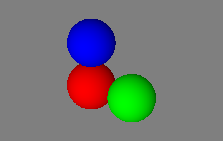
Ray tracing spheres with orthographic camera rays.